Heat Process Modelling
Contents
1. Introduction
PLEXOS is an Integrated Energy Model, bringing together Electric, Gas, Water and Heat Models. The new heat class feature allows users to model the production, transportation and consumption of the heat resources. The heat class will be co-optimized with other existing systems such as electricity, gas and water in the integrated model. Some applications of the heat class are modelling the Combined Cycle Gas Turbine (CCGT), water treatment plants and other heat-related operations. The simulator provides these classes for the heat process simulation:
| Class | Description |
|---|---|
| Heat Plant | Produce heat from burning fuels, recover waste heat or convert electricity to heat (electric boiler). |
| Heat Node | Connect the heat supplying sources to heat consuming sources. It can also be used to model the heat transportation between heat nodes. |
| Heat Storage | Stores heat for use after initially being produced. |
In addition, other existing classes can also be used in a heat model as heat suppliers (generator) or heat consumers (generator, water plant).
Note that, there are some existing features to model the heat process in PLEXOS such as using Heat Input, Heat Output (in generator object) or Heat Market. At the time of writing this article, these existing features should not be used together with the new heat modelling.
2. Heat Model
2.1. Network Definition
The Heat Model is composed of 3 main types of objects, namely heat supplier, heat consumer and heat node. These connect together as shown in Figure 1.
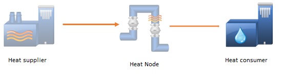 Figure 1: Heat Model
Your Heat Model may include any number of these objects in any configuration.
2.2. Heat Supplier
Heat suppliers are facilities that supplying heat to the heat nodes that are attached to them. Currently, there are two objects that can supply heat in PLEXOS, namely generator and heat plant.
Generator
Any thermal generator can supply waste heat to the heat nodes attached to its Heat Output Nodes. Waste heat is the by-product heat of the main power generating process.
Generally speaking:
Heat Output Node <= Waste Heat = Fuel Off-take + Heat Input (from Heat Input Nodes) - 3.6 × Generation
If a generator has a heat storage and/or a heat load then its heat output is calculated as:
Heat Output Node <= Waste Heat + Heat Release - Heat InFlow - Heat Load
Note that the heat output of a generator can be linked to many heat nodes. Participation Factor is used to define the proportion of generator output injected at the node. Using this property, you can split a Generators output across multiple Nodes. Participation factor (<1) can also be used to describe the efficiency of the waste heat recovery process. It is also noted that excess heat can be dumped in the heat output nodes. Currently, only heat storage and heat load is compatible with the heat output nodes feature. Other existing heat terms such as Heat Input, Heat OutPut, and Heat Market do not work well with this feature.
Heat Plant
Heat Plant is a special object that produces heat from burning the fuels, and/or recovering waste heat and/or converting the electricity to heat. To the electrical network, heat plant is a load source (anti-generator). The overall efficiency of the heat plant is defined through the property Efficiency Incr and/or Efficiency Base.
Heat Output Node = Fuel Off-take + Heat Input (from Heat Input Nodes) + 3.6 × (Electric Load)
2.3. Heat Consumer
Heat consumers are facilities that receiving heat from the heat nodes that are attached to them. Currently, there are two objects that can consume heat in PLEXOS, namely generator and water plant.
Generator
Generator is also consuming heat as well as generating heat. Attaching the heat nodes to the Heat Input Nodes of a generator will define that this generator is receiving heat from those heat nodes. Input heat will be used together with other input heat sources (such as fuel inputs) to produce electricity. A generator can link to many heat nodes, the total heat input will be sum of all the heat these nodes can supply to this generator. Note that this behavior is different from that in the Heat output nodes whereas the distribution is based on a user-defined participation factor.
Heat Plant
Generator is also consuming heat as well as generating heat. Attaching the heat nodes to the Heat Input Nodes of a heat plant will define that this heat plant is recovering heat from those heat nodes.
Water Plant
Water plant receives heat through its heat node to produce water. The heat usage property is defined to model how much heat energy this plant will need.
Heat Node
The heat demand property is defined the heat load demand at the heat node.
2.4. Heat Storage
Heat storage objects are both heat consumers and suppliers as they receive heat from their connected heat node and send that heat back into the network for later use after initially being produced.
2.5. Heat Node
Heat node objects are used to connect the heat supplying sources to heat consuming sources. In addition, a heat node can be linked directly to other heat nodes to model a heat pipe or heat by-pass. Note that heat nodes do not have storage capability, which means excess heat injection will be dumped on the node.
Net Heat Injection = Heat Injection (from supplying sources) - Heat Withdrawal (From consuming sources) - Heat Dump - Heat Demand
If a heat node is exporting heat to another heat node, the amount of export heating to that node will be:
Heat Export = Net Heat Injection
3. Some Example Applications
3.1. Combined Cycle Gas Turbine (CCGT)
To model a CCGT configuration, a common heat node is created and then GT generators connect to this node via the Heat Output Nodes while ST generators are linked by their Heat Input Nodes. Other feature such as boilers or fuels can be added if necessary. Example: a CCGT configuration (3 GT and 1 ST) can be achieved by creating a heat node and connecting it to the heat output nodes of the primary generators and heat input nodes of secondary generators.
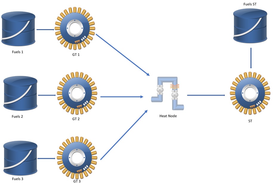 Figure 2: a CCGT configuration
Note that, currently PLEXOS has another method to model the CCGT through defining the relation between generators in Heat Input and Heat OutPut. This method and the new heat node feature should not be used together in a same object.
3.2. Desalination and CCGT
The new heat class is useful to model a desalination water plant, in which a water plant receives waste heat from a power plant as energy to produce fresh water from sea water. In the below example, the Gas turbine generators produce waste heat, which is collected by the Heat Recovers HRSG1. Heat Recovers top up heat by fuels input or electricity. Heat from heat recovers will go directly into the water treatment plant through the ST bypass heat. Alternatively, it can provide heat to the steam turbine generator and the waste heat after ST will go into the water plant.
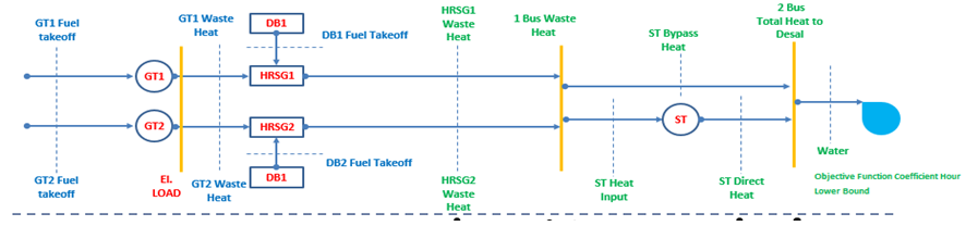 Figure 3: Water and Co-gen configuration
This can be achieved by the new classes such as:
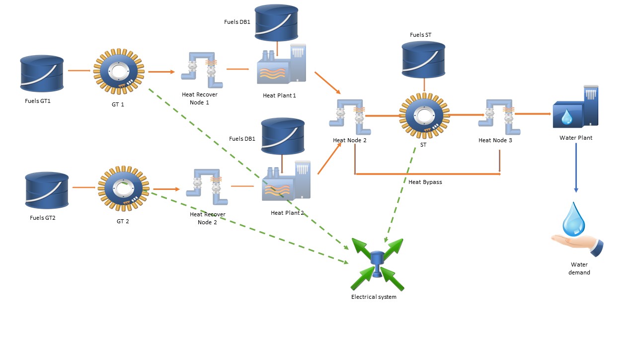 Figure 4: Water and Co-gen configuration using the new heat class
4. FAQ
- Why doesn't a Heat Plant exist in the simulation or appear in the solution database?
Like a generator object, a heat plant object requires at least a defined [Unit] property and [Max Capacity] to be active in the simulation.
- Why is the heat withdrawal in the heat node smaller than the heat injection to the node?
Waste heat is normally produced more than demand and heat is normally dumped in the heat node.
- Why is the heat output from a generator zero or very small even though it is running?
The generator can also dump away the heat and only deliver the necessary amount of heat to the heat output nodes.
- Why do the input heat nodes and output heat nodes seem to be inactive during the simulation?
Temporarily the input heat nodes and output heat nodes do not work with existing heat processes such as heat market and CCGT configuration.
- Which existing heat functionalities will be compatible with the new heat class feature?
CHP, heat storage and heat load.
- How to model the efficiency in the new heat class feature?
In heat plant, use property [Efficiency Incr]
In generator, use the property [Participation Factor]
In heat node to heat node, use the property [Participation Factor]
- Can a heat plant/ generator/ water plant connect to more than one heat nodes? What is the expected behavior?
A heat plant/generator/water plant can connect to more than one node if it is enabled in the configuration. However, the behaviour is different between the input heat node and the output.
-Input heat nodes: (generator and water plant). In this case, the heat input is the sum of the heat withdrawing from those nodes:
Heat Input = HeatWithDrawal(Heat Node 1) + HeatWithDrawal(Heat Node 2) + ... + HeatWithDrawal(Heat Node N)
Each amount of heat withdrawal is an independent decision variable and PLEXOS will choose the optimal amount of heat to withdraw from each node.
- Output heat nodes (generator and heat plant): the amount of heat a generator is supplying to a heat node will depend on the participation factor.
HeatInjection(Heat Node 1) = (Heat OutPut) * (Participation factor(Heat Node 1) )
HeatInjection(Heat Node 1) = (Heat OutPut) * (Participation factor(Heat Node 1) )
...
...
...
HeatInjection(Heat Node N) = (Heat OutPut) * (Participation factor(Heat Node N) )
Note that if participation factor is not defined, PLEXOS will optimally choose the participation factor.
Heat Output = HeatInjection(Heat Node 1) + HeatInjection(Heat Node 2) + ... + HeatInjection(Heat Node N)
Each amount of heat injection is an independent decision variable and PLEXOS will choose the optimal amount of heat to inject to each node. This behaviour is controlled by an undocumented parameter "RequireOptimalHeatSplit" (see Undocumented parameters).
- Why does the water plant not produce any water after defining the heat usage property?
Water plant needs to be connected to a heat node to receive heat to meet its heat usage demand.
- How to control the steam by-pass?
Steam by-pass is defined in PLEXOS as the direct connection between two heat nodes (using Heat Export Node membership). If a generator also serves as a connection between these two nodes, the operation of the bypass will be controlled by the generator in 3 different modes:
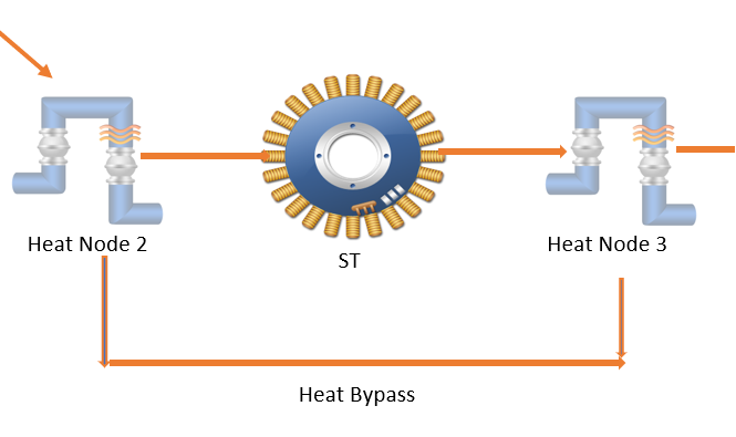 Steam by-pass
- "Free" mode: the operation of the by-pass is not controlled by the generator.
- "Outage" mode: the bypass can only open if the generator is out of service (outage or has maintenance). If there are more than two generators connecting to the same bypass, bypass is open only when all of them are out of service
- "Commitment" mode: the bypass can only open if the generator is not committed.
The default behaviour is set as "outage" mode. To change the mode, an undocumented parameter "SteamByPassControlMode" can be used (see Undocumented parameters).
- Modelling a condenser for Steam Turbine generator?
By default, the steam turbine generator is equipped with a condenser. This means that it can recover all the heat from its heat input node and technically speaking can operate just as a steam bypass. If there is any ST generator that does not have a condenser in the model, user can specify those generators using an undocumented parameter "STGeneratorsWithoutCondenser" (see Undocumented parameters).