Settings
Contents
- Introduction
- Unit systems for entering Data
- Locks
- Messages
- Custom Messages
- Custom Columns
- Assemblies
1. Introduction
The settings form controls the following preferences related to the current database:
- The unit system used for entering data.
- Locks on data and Scenario objects that prevent accidental data changes.
- Preferences for the handling of error and warning messages during the simulation.
- The list of custom assemblies to be loaded at run time to perform custom actions.
2. Unit systems for entering Data
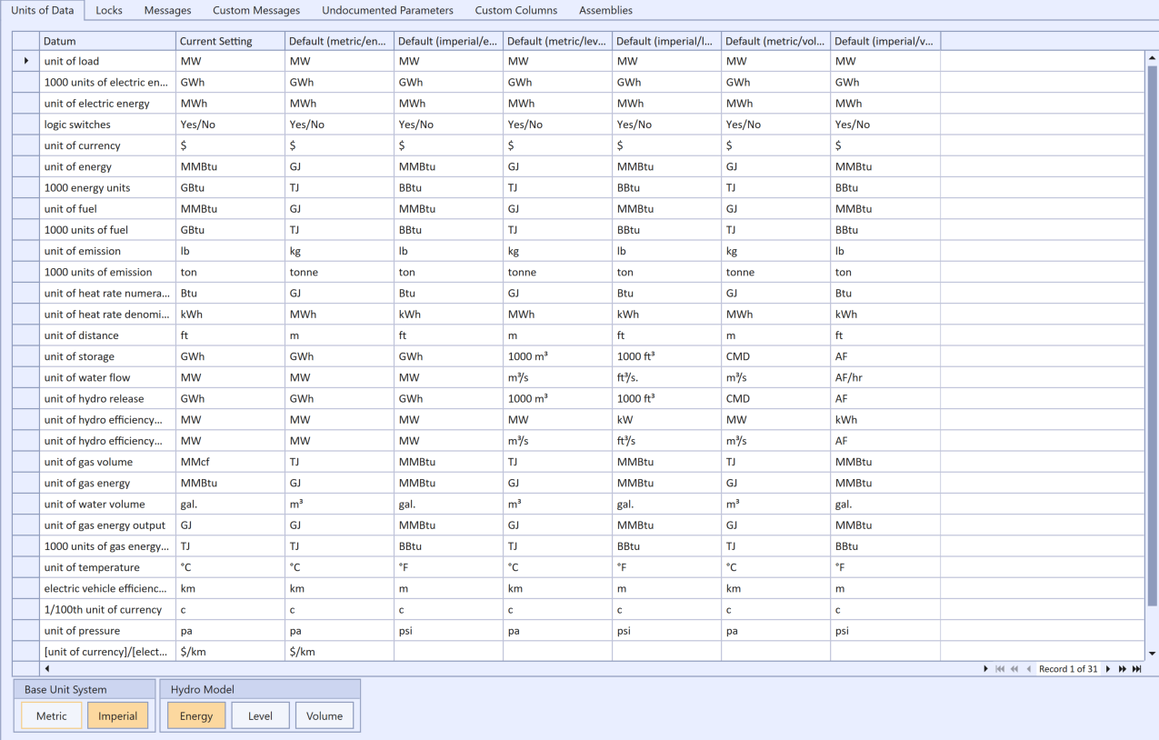
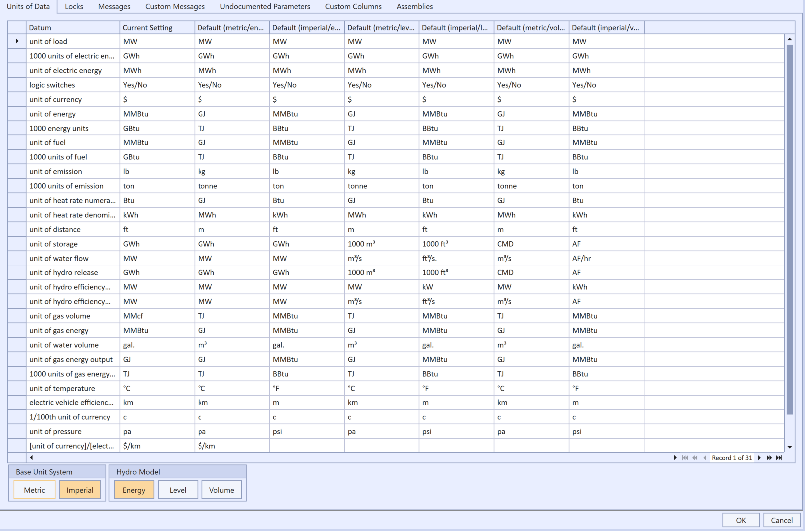 Units of Data Tab
The simulator supports tow unit systems (metric and Imperial US) and, within that, three systems for defining hydro data. In addition you may change the unit for electric load and energy e.g. switch form megawatt (MW) to kilowatt (kW) for small systems.
2.1. Electric Load and Energy
It is important to note that the simulator uses the symbols you enter for units only as labels. It does not attempt to interpret the labels. Thus if you change the electric load unit from the default megawatt (MW) to kilowatt (kW) you must also change the other system units so that the relativity between units is maintained. This is illustrated in Figure 2 where the electric load unit has been changed to kW and all other units have been scaled down three orders of magnitude.
 Electric Load as Kilowatt
2.2. Metric
Defines:
- Incremental heat rates in giga-joules (Gj) per megawatt-hour (MWh) e.g. 9.5 GJ/MWh.
- Heat rate base values (no-load cost) in GJ e.g. 200 GJ/hr
- Fuel prices in dollars (or other currency) per giga-joule ($/GJ)
- Total fuel use is in tera-joules (TJ)
- Emissions production in kilograms (kg)
- Total emissions in tonnes (where one tonne = 1000 kg)
2.3. Imperial U.S.
Defines:
- Heat rates in British thermal units per kilowatt-hour (BTU/kWh)
- Heat rate base values (no-load-cost) in millions of BTU (MMBTU)
- Fuel prices in dollars per million BTU ($/MMBTU)
- Total fuel use is in millions of BTU (MMBTU)
- Emissions in pounds (ib)
- Total emissions in short (US) tons (where one ton = 2000 ib)
Three key calculations are affected by the selected units system:
- Generator fuel usage as heat rate × generation. In the Imperial U.S. system the heat rate is scaled down by a factor of 1000 (to convert from kWh to MWh), but in the Metric system no conversion is required. For example, if a generator is 40% efficient its Metric heat rate is entered as 3.6 / 0.4 = 9 GJ/MWh, but in the Imperial U.S. system its heat rate is entered as 3.412 / 0.4 = 8530 BTU/kWh. Note that the second-order heat function term is scaled internally by 1E+6, the third by 1E+9, etc.
- When summarizing emissions from either fuels or generators the Metric model defines one unit in summary (day, week, month, year) as 1000 of the base units, whereas the Imperial U.S. model uses 2000 units. Thus if you define a constraint on total emissions over a day, week, month or year you must should enter the limit in the appropriate unit e.g. if the production rate is in lb/MWh then an annual constraint would be in short tons, where one short ton equals 2000 lbs.
2.4. Hydro Model
The Hydro Model selection affects the units used to define hydro storage and hydro generator efficiency. There are three options available:
- Energy (also called Potential Energy)
- Level
- Volume
2.4.1. Energy
This model makes these assumptions:
- That storage volumes are measured in potential energy, not volumes of water. The potential energy in a storage is a function of generation efficiency of all power plants downstream of the storage.
- Generator efficiencies are static i.e. each station produces megawatts on a one-to-one with 'water' (potential energy) used.
- There are no pump storage units in the chain or diversions that mean the potential energy of water in each storage is not static.
Hence, this model is suitable only for simple 'linear' cascaded systems.
2.4.2. Level
The Level Model uses elevations (e.g. above sea level) and reference areas. In metric mode the storage elevations are in metres (m), storage volumes are measured in thousands of cubic metres, and flows are measured in cubic metres per second (cumecs). In imperial mode the storage elevations are in feet (ft), storage volumes are measured in thousands of cubic feet, and flows are measured in cubic feet per second (ft3/sec).
In this model, storages are assumed to form a trapezoid shape (defined by the properties Low Ref Level, Low Ref Area).
Unlike the potential energy model, here you must define the efficiency of generation using Efficiency Incr and Efficiency Base. Generator efficiencies are measured in megawatts per cubic metres per second (MW/cumec) in metric mode, and in megawatts per cubic feet per second (MW/ft3/sec) in imperial mode.
2.4.3. Volume
In the Volume model, the unit of storage is a volume of water, rather than levels or potential energy. Hence you must define the efficiency of generation using Efficiency Incr and Efficiency Base.
In metric mode:
- Storage volume in cubic metre days (CMD).
- Flows in cubic metres per second (cumec).
- Generator efficiencies in megawatt per cubic metres per second (MW/cumec).
In imperial mode:
- Storage volumes in acre-feet (AF).
- Flows in acre-feet per hours (AF/hr).
- Generator efficiencies in kilowatt hours per acre-feet (kWh/AF).
2.4.4. Hydro Unit Conversions
| Unit | Equivalent |
|---|---|
| 1 acre | 43,560 square feet |
| 1 feet | 0.3048 metres |
| 1 cubic metre | 35.3146667 |
| 1 acre-feet | 1233.489238 |
| 1 cubic metre per second (cumecs) | 4600 cubic metres per second |
| 1 acre-feet | 0.3426 |
| 1 cumecs | 2.9186 acre-feet |
| 1 cumec day (CMD) | 86400 cubic metres |
| 1 CMD | 24 cumecs |
| 1 CMD | 70.0456 acre-feet |
3. Locks
 Locks tab
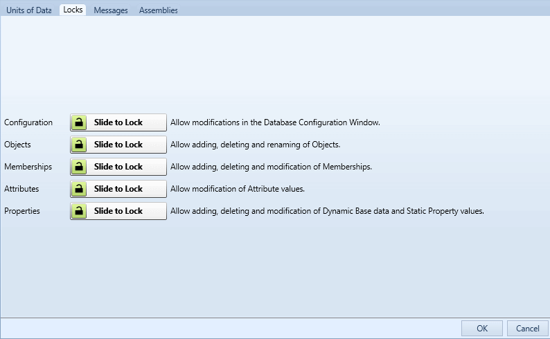
To protect data from accidental change you can lock various parts of the database to editing. The Locks tab contains the controls as shown in Figure 2.
Configuration
Locks or unlocks the Configuration window. Locking this prevents the user from enabling or disabling features such as collections and properties or changing the dynamic/static status of properties. The Configuration screen is still accessible but is placed in a read-only state.
Objects
Locks or unlocks the Objects grid. Locking this prevents adding, deleting, editing or renaming any object. The Objects grid is placed in a read-only state as are the name, category and description controls on the class forms.
Memberships
Locks or unlocks the Memberships grid. Locking this prevents adding, deleting or editing memberships.
Attributes
Locks or unlocks object attributes. This applies particularly to simulation settings pages. Locking this prevents the user from changing simulation options such as Production or Transmission settings.
Properties
Locks or unlocks properties. Locking this prevents adding, deleting or editing properties. There are two levels to this control as described below.
The Scenario Locked attribute allows you to choose which data can be edited and which are locked. For data that are not marked with a Scenario the Properties Lock option directly controls the lock/unlock status. But for data marked with a Scenario the Scenario attribute Locked controls the locking. The row marker for the Properties Grid shows a lock symbol for the rows that are locked (the base data). The Scenario data are by default Unlocked.
The locks are enabled or disabled by sliding the lock image across the slider control. Figure 3 shows the options all in the locked state.
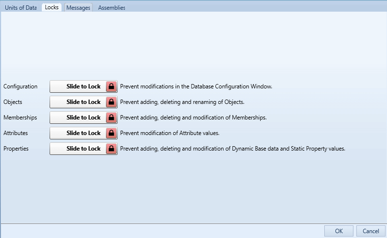 Locks enabled
4. Messages
 Messages tab
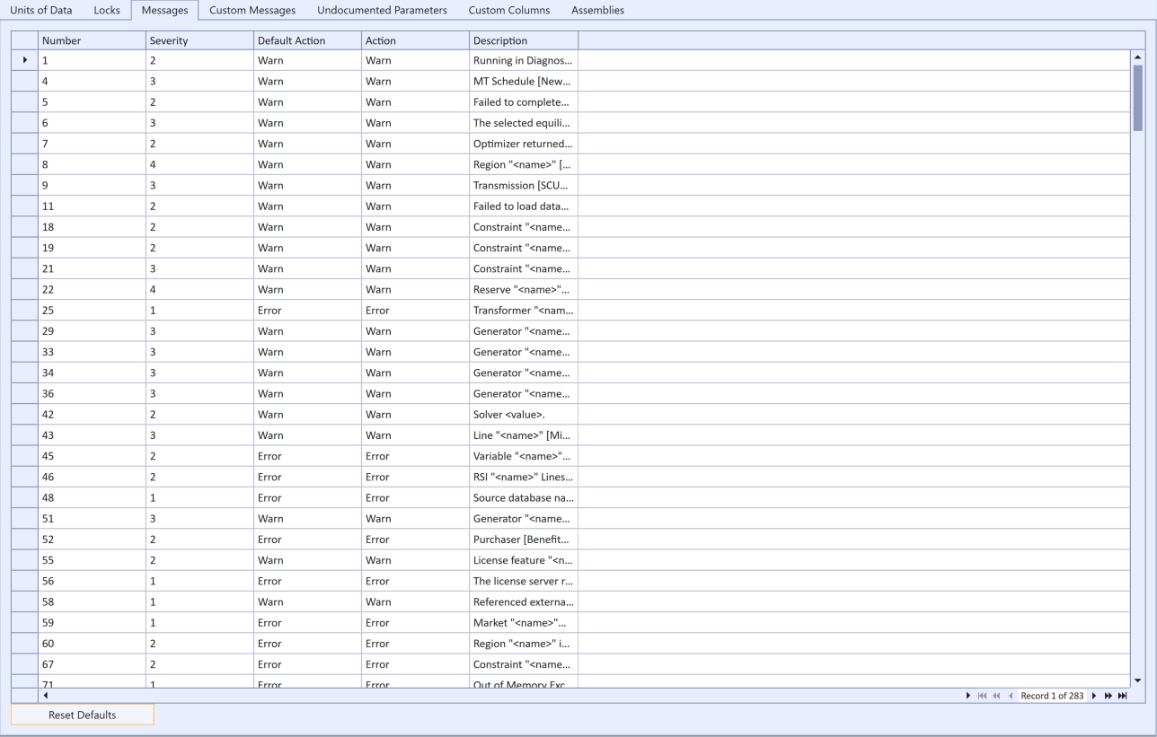
The Messages tab, pictured in Figure 4, sets preferences for the handling of error and warning messages produced by the simulator. The columns of the grid are:
Number
The unique identifier for the message.
Severity
An indication of the severity of the issue described in the message. The levels of severity are described below.
Default Action
The action that the simulator normally takes this message.
Action
The action you prefer the simulator to take for this message.
Only the Action field can be edited. You may choose one of the following:
Error (value = 0)
An error is raised when this message appears. The error will stop the simulation immediately.
Warn (value = 1)
A warning is produced every time this message is raised by the simulator.
Warn Once (value =2)
A warning is produced only the first time this message appears in any one simulation
Ignore (value =3)
The message is hidden during the simulation and only listed along with the number of occurrences at the end of the simulation.
When the Action is changed from default the corresponding row in the table is shown in bold text as in Figure 5 where Message 210 Action has been changed from "Warn" to "Error". You can use the "Reset Defaults" command button to restore all messages to their default actions.
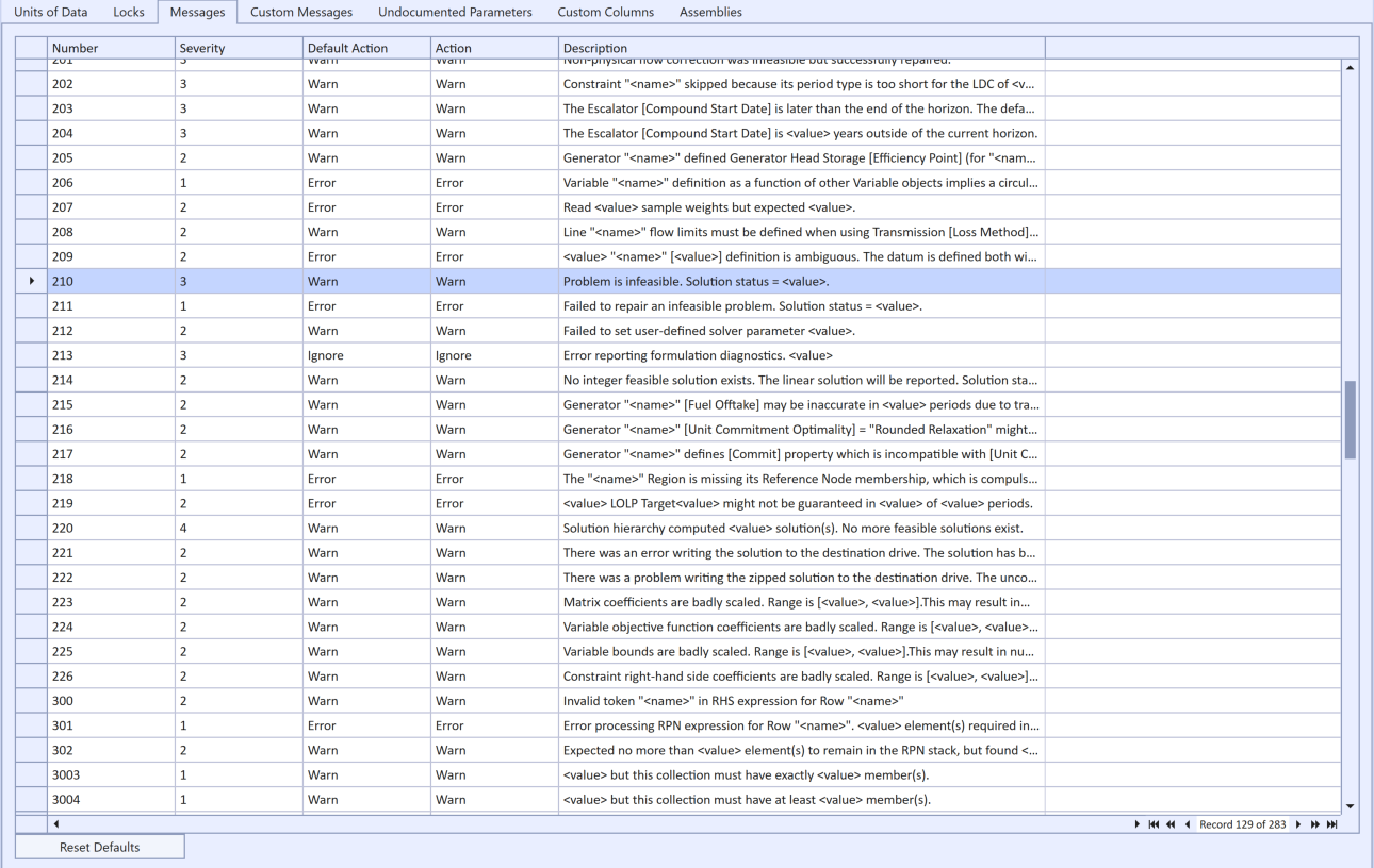 Message Action set non-default
For help on the individual messages, press F1 while a row of the table is highlighted or refer to the Error and Warning Messages topic.
Message severity is rated according to the following scale:
Fatal (value=1)
This error either cannot or should not be ignored. In most cases the simulation cannot continue until this error is rectified.
Serious (value = 2)
This issue could seriously affect either the simulation performance and/or results though the simulation can continue.
Moderate (value = 3)
This issue might not affect the simulation results but is serious enough to warrant a warning message.
Minor (value = 4)
This message is provided for information only.
At the end of every Model log a listing is given of all messages raised by the simulator - regardless of the Action setting. This log table lists, the message, number, severity, action taken and the number of times the message arose. Thus even if you choose to ignore a message during the simulation you may still see the number of times it would have appeared from this table. An example is below:
--------------------------------------------------------------------------------------------------------------------------------
Error and Warning Messages for Model "Test":
--------------------------------------------------------------------------------------------------------------------------------
Number    Description                                                                               Severity  Action    Count
--------------------------------------------------------------------------------------------------------------------------------
42        Solver <value>.                                                                                  2      Warn         2
210       Problem is infeasible. Solution status = <value>.                                                3      Warn         4
214       No integer feasible solution exists. The linear solution will be reported. Solution s...         2      Warn         2
--------------------------------------------------------------------------------------------------------------------------------
5. Custom Messages
 Database Settings Window - Custom Messages
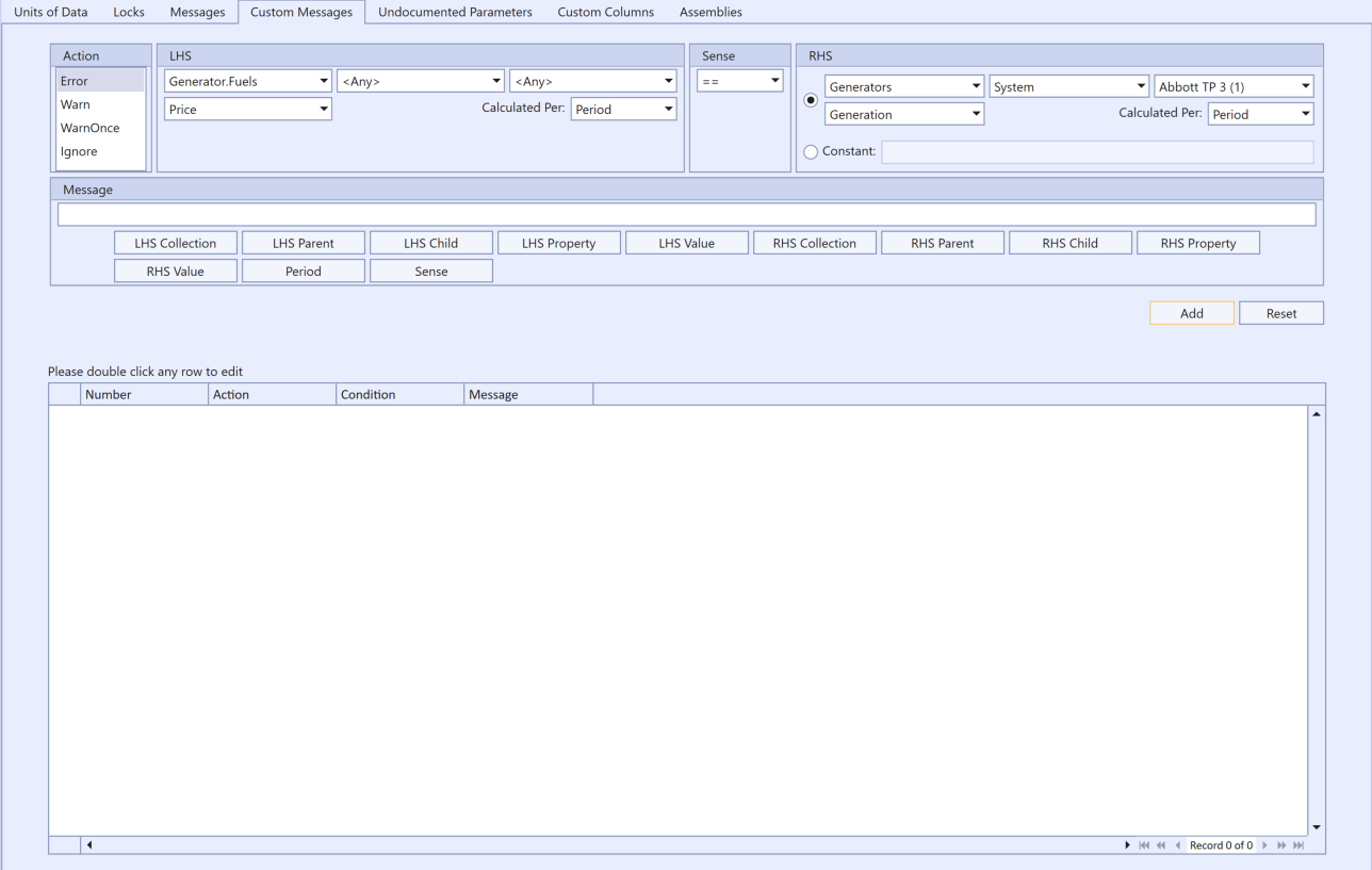
Custom messages can be defined in a PLEXOS database to be used by PLEXOS Engine during execution. This allows you to add your own conditions to the PLEXOS engine, preventing simulations from continuing or creating warnings if specific conditions are met.
When creating a new custom message, you will be able to define:
- The action to take when the condition is met, this is the same as above in 'messages' (ie, 'Warn', 'Error', etc).
- Left hand side of the equation as a property.
- Right hand side can be defined and right hand should be equal, not equal, etc.
- Whether the left hand and right hand should be equal, not equal, etc.
- A message to be displayed when the condition is true.
The message field accepts macros, allowing messages to have the actual values from during the simulation be displayed in the message when its condition is met. These macros are all listed underneath the message field and clicking any of the macro buttons will insert that macro into the message. As an example using the first custom message rule from the image above, the message '{lhs_child} ({lhs}) is not equal to {rhs_child} ({rhs}) in period {p}.' may get changed to 'Gen1 (20) is not equal to Region1 (30) in period 3.'
The custom messages can also be imported and exported by selecting the 'Import' or 'Export' button in the ribbon menu. This allows you to use the same custom messages across multiple different databases. Please note that any custom messages with duplicated number values will be overwritten by the imported value.
6. Undocumented Parameters
 Database Settings Window - Undocumented Parameters
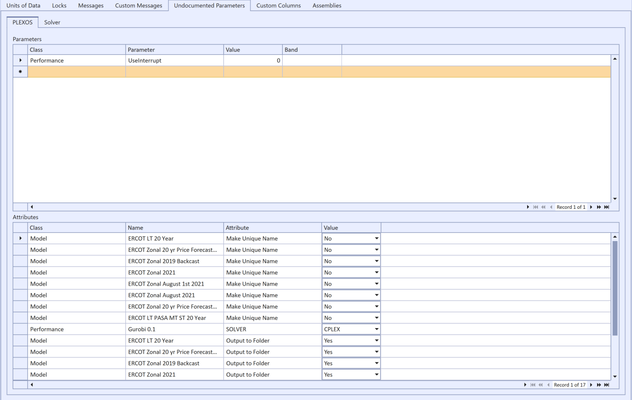
The Undocumented Parameters tab is a UI for creating PLEXOS_Param.xml and PLEXOS_SolverParam.xml files. There are a number of hidden or 'undocumented' control parameters specific to the version of the simulator that are now available through the PLEXOS interface. For more details on the available parameters and values refer to Undocumented Parameters. They will change from version to version.
- Class specifies the class of the simulation object
- Name uniquely identifies the object of type Class which is being modified
- Attribute specifies the attribute which is being modified
- Value specifies the value the attribute is being changed to
- Save the database to access the Undocumented Parameters editor. If the database is not save, the screen is greyed out.
- Anything specified in the Class and Attribute tags in "PLEXOS_Param.xml" must conform to the names used in "class_id" and "name".
- All values in the Value tags are to be of type double.
- All date information uses a format called the OLE Automation Date. It's a floating point number, which is the number of days since 31st December, 1899. It is easy to obtain that number using Excel by formatting a cell as a number and it will automatically convert the date (i.e., 1/12/2022 to 44573.416).
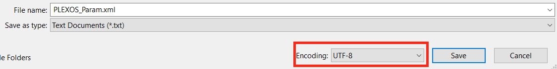
- If any simulation objects use foreign characters in their name, please ensure PLEXOS_Param.xml is saved with UTF-8 encoding. To save a text file as UTF-8 will depend on the text editor you use, but almost all text editors, even Windows' Notepad, has an option for how to encode text. UTF-8 is usually the default anyway. In Notepad, when you go to save, you will see the following option:
- Caution is advised when changing attributes as some might require other attributes to be modified that might not be obvious at first.
7. Custom Columns
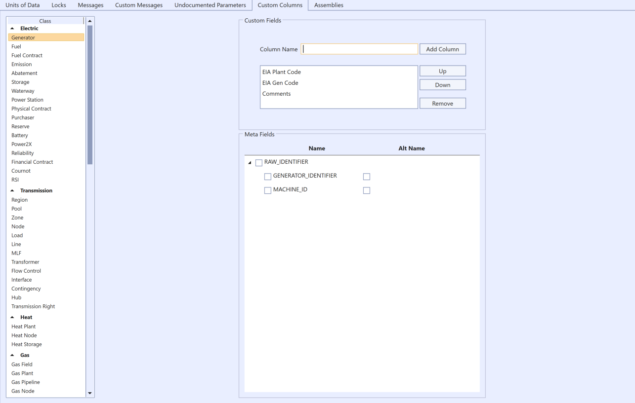 Database Settings Window - Custom Columns
Custom columns can be added to the Object grid to store additional information for each object. Select which class you want to annotate and add any number of additional information columns to appear in the object grid.
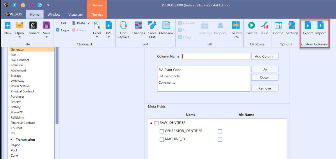 Database Settings Window -Export/Import Custom Columns
Custom columns can also be imported or exported by selecting the 'Import' or 'Export' buttons on the ribbon menu. Any duplicate column names in the importing file will be ignored during the import process. Note that the 'Import' button will only be enabled when the 'custom columns' tab is selected, and the 'Export' button will be enabled only when the 'custom columns' tab is selected and the input database contains any custom column in it. After a successful import or export the system will pop-out a confirmation dialog box.
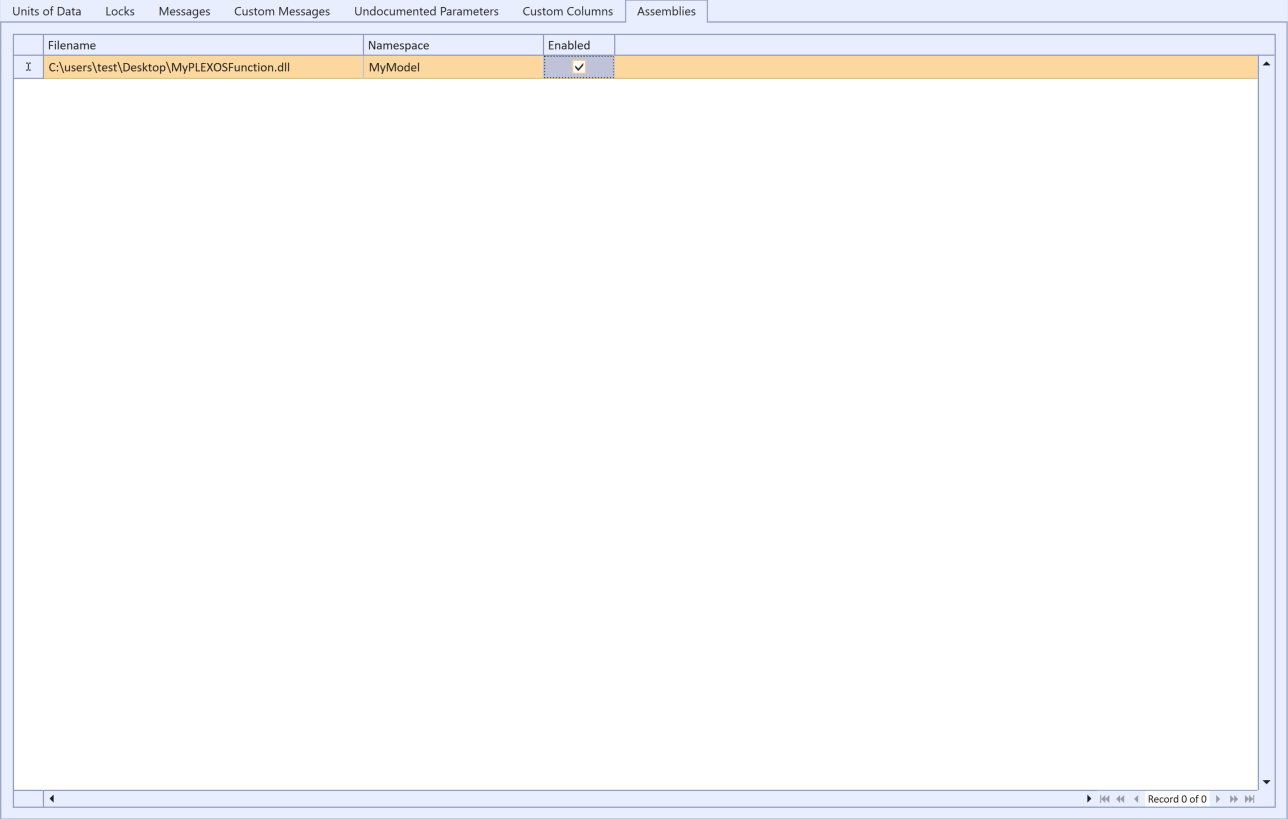
7. Assemblies
 Assemblies tab
The assemblies tab is the location for specifying custom dynamic link libraries complied for OpenPLEXOS See the Customizing topic for more information.