Hydro Classes
Contents
1. Introduction
There are a multitude of ways to model hydro generators and networks of storage in the PLEXOS software. The classes that provide the fundamental building blocks (in order of importance) are:
- Generator
- Storage
- Waterway
- Constraint
This section begins by describing how the generic Generator class can be used to model hydro generators in a basic fashion. Later sections build up to exploring more complex modelling features.
2. Generators
Hydro generators can be modelled to various levels of complexity
Energy-constrained GeneratorThe simplest approach is to define energy constraints to approximate the availability of water (using Generator Max Energy Day|Week|Month|Year, and Max Capacity Factor Day|Week|Month|Year), and a profile of minimum operating levels that represent run-of-river generation (Generator Min Load) as in Table 1.
Table 1: Simple energy-constrained hydro with run-of-river| Property | Value | Units | Pattern |
|---|---|---|---|
| Units | 1 | - | - |
| Max Capacity | 60 | MW | - |
| Min Load | 5 | MW | M1-4, 10-12 |
| Min Load | 15 | MW | m5-9 |
| Max Energy MONTH | 15 | GWh | m1-4,10-12 |
| Max Energy MONTH | 2 | GWh | m5-9 |
You may use any of the day, week, month or year versions of Max Energy. The energy limit applies across all units in aggregate, not unit-by-unit. Perhaps a more convenient alternative is to use Max Capacity Factor Day|Week|Month|Year which is entered as a percentage value rather than in GWh and will 'flex' as the number of units at the generator changes.
NOTE:
If you are running ST Schedule these properties may require use of MT Schedule so that the constraints are decomposed into equivalent shorter-term constraints that ST Schedule can resolve.
Pump Storage
Pumped storage plants must have a Head Storage and a Tail Storage defined. In addition you must define the properties Generator Pump Efficiency and Pump Load as in Table 2. You may optionally define Pump Units and Min Pump Load. Pumped storage is most commonly modelled as a closed system, i.e. no energy flows into or out of the head or tail storages other than from generating or pumping, but any configuration is possible: see Pumped Storage.
Table 2: Simple pumped storage generator
| Property | Value | Units |
|---|---|---|
| Units | 1 | - |
| Max Capacity | 240 | MW |
| Pump Load | 240 | MW |
| Pump Efficiency | 70 | % |
Hydro in a Cascade Different type of hydro units: run-off river, mini-hydros, small/medium/ large dam reservoirs, can be modelled properly defining memberships between the Generator objects and Storage and Waterway objects. Turbine type can be captured by defining the Hydro efficiency Generator Efficiency Base and Efficiency Incr properties: see Hydro Generator Efficiency and Head Effects for details.
In a cascading hydro network, flows through the generator are set up by adding a Generator Head Storage membership and optionally a Tail Storage. Spillways, river runs and canals are modelled with Waterway objects. Waterways can connect different storage using the Storage From and Storage To memberships.
3. Storages
Storages are used to represent storage reservoirs with short, medium, or long-term storage, generator head-ponds and tail-ponds, or even simple junctions in a river-chain. Storage objects are created in the same way as any other object. Each storage can connect to one or more generators or waterways to create a model of a river chain.
In general there are three 'types' of storage:
- Pumped storage reservoirs see the article Pumped Storage
- Short-term storages (such as head-ponds and tail-ponds) whose storage tends to cycle over days or weeks;
- Long-term storages whose 'water value' is either calculated exogenously or determined over a long-term horizon see the article Pumped Storage
There are multiple options for the units of storage. Both a database-wide setting (Hydro Model) and individual object settings (Storage Model) exist. Primarily you choose between a volume-type model (where Storage is either in potential energy or volumes of water) and a level-type model where Storage is measured in elevation. For these models then Storage capacity is defined by either:
NoteWhen using the level approach you define the storage size using the set of properties Low Ref Level, Low Ref Area, High Ref Level, High Ref Area.
Minimum allowed storage is defined using:
- Min Volume; or
- Min Level
Initial (period 'zero') storage is defined with"
Storage inflows are defined using the Storage Natural Inflow property. Typically this is a dynamic property with values specified hourly or as daily, weekly, or monthly averages.
Storage optimization can be deterministic or stochastic. For stochastic optimization the property Storage Trajectory Non-anticipativity flags storages whose trajectory cannot be deterministically optimized: see Pumped Storage.
Constraints can be placed on the amount of release from the storage in any period using the Storage Min Release and Storage Max Release properties. The rate of change of release can be limited using Storage Max Ramp.
To handle end-effects, storages can be:
- Driven to target levels using Target Day|Week|Month|Year; or
- Have releases governed by the user-defined Shadow Price of water in storage; or
- Automatically recycled to their Level (if defined) or an optimized initial position by setting the attribute Storage End Effects Method = "Recycle".
By default PLEXOS will choose which storages require decomposition of their medium-term trajectory from MT Schedule (or LT Plan) to ST Schedule. The default can be overridden using the Decomposition Method attribute: see Cascading Hydro Networks.
4. Waterways
Waterway objects either:
- Connect the storages in their storage from and storage to collections; or
- Spill water from the storage from 'to the sea'.
Combinations of Storage, Waterway, and Generator objects are used to create models of cascading hydro networks with canals and spillways modelled with waterways.
Waterway flows can be delayed using the Waterway Traversal Time property.
Waterways can have bounds placed on their flows using the Waterway Max Flow and Min Flow properties. The units for these limits, and for reported waterway flows is controlled by the Hydro Model database setting. If required (particularly for "Potential Energy" Hydro Model) you can scale the input to a waterway using the Waterway Input Scalar property.
The rate of change of flow can be controlled using the Waterway Max Ramp property.
Note that the penalties applied to violation of waterway minimum flow limits and ramping limits are controlled by the Production attributes Hydro Min Flow Penalty and Hydro Flow Delta Penalty respectively.
When a waterway is acting as a spill, either from one storage to another, or 'to the sea', there can be circumstances in which the optimal solution is to spill water even though the storage is not full. This behaviour can be overridden using the Waterway Flow Control flag.
5. Constraints
Constraint objects are used to define custom constraints on elements or combination of elements in your hydro system. Constraints can include Generators, Storages, and Waterways in any combination. The following coefficients related to the hydro model are available:
Table 3: Common hydro related coefficient for custom constraints
| Collection | Property | Description |
|---|---|---|
| Constraint generators | Generation coefficient | Generation (electrical output) coefficient. |
| Constraint Generators | Pump Load Coefficient | Pumping load variable coefficient (in MW) |
| Constraint storage | End volume coefficient | End volume variable coefficient. End volume variable is used in the water balance constraint: End Volume=Initial Volume+Inflows-Releases |
| Constraint storage | End Volume Delta Coefficient | End volume differential (across periods) coefficient |
| Constraint Waterway | Flow coefficient | Waterway's flow variable coefficient |
| Constraint Waterway | Flow Delta Coefficient | Coefficient of ramp variable in max flow ramping constraints |
6. Hydro Model
The first step in moving beyond potential energy modelling in your cascading hydro network is to set the units used to model the hydro storages and hydro generator efficiency functions. This is done through the Settings form as in Figure 1.
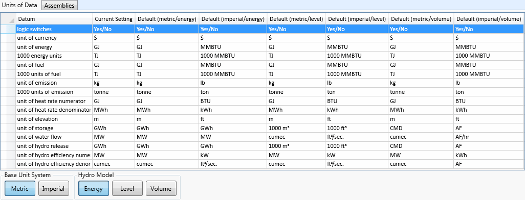 Figure 1: Units of Data Settings
The hydro model selection sets the units used to define hydro storage and hydro generator efficiency. There are three options available:
- Energy (Potential Energy)
- Level
- Volume
Energy
As discussed above, this model makes the following assumptions:
- Storage volumes are measured in potential energy, not volumes of water. The potential energy in storage is a function of generation efficiency of all power plants downstream of the storage.
- Generator efficiencies are static i.e. each station produces megawatts on a one-to-one with 'water' (potential energy) used.
- There are no pump storage units in the chain or diversions that mean the potential energy of water in storage is not static.
Hence this model is suitable only for simple 'linear' cascaded systems and stand-alone (closed-circuit) pumped storage models.
Level
The Level model uses elevations (e.g. above sea level) and reference areas. Storages are modelled as trapezoidal meaning that surface area increases as they fill up. In metric mode the storage elevations are in metres (m), storage volumes are measured in thousands of cubic metres, and flows are measured in cubic metres per second (cumec). In imperial mode the storage elevations are in feet (ft), storage volumes are measured in thousands of cubic feet, and flows are measured in cubic feet per second (ft3/sec).
In this model, storages are assumed to form a trapezoid shape (defined by the properties Storage Low Ref Level, Low Ref Area. Unlike the potential energy model, here you must define the efficiency of generation using Generator Efficiency Incr and Efficiency Base. Generator efficiencies are measured in megawatts per cubic metres per second (MW/cumec) in metric mode, and in megawatts per cubic feet per second (MW/ft3/sec) in imperial mode.
Volume
In the Volume model, the unit of storage is a volume of water, rather than levels or potential energy. Hence you must define the efficiency of generation using Generator Efficiency Incr and Efficiency Base.
In metric mode:
- Storage volume in cubic metre days (CMD);
- Flows in cubic metres per second (cumec);
- Generator efficiencies in megawatt per cubic metres per second (MW/cumec).
In imperial mode:
- Storage volumes
- Flows in acre-feet per hour (AF/hr)
- Generator efficiencies in kilowatt hours per acre-feet (kWh/AF)/
| Unit | Equivalent |
|---|---|
| 1 acre | 43, 560 square feet |
| 1 feet | 0.3048 metres |
| 1 cubic metre | 35.3146667 |
| 1 acre-feet | 1233.481838 |
| 1 cubic metre per second (cumecs) | 3600 cubic metres per hour |
| 1 acre-feet per hour | 0.3426 |
| 1 cumecs | 2.9186 |
| 1 cumec day (CMD) | 86400 cubic metres |
| 1 CMD | 24 cumecs x hour |
| 1 CMD | 70.0456 acre-feet |
7. Hydro-Thermal Coordination
This section develops an example hydro-thermal coordination model as a way of demonstrating:
- A basic storage model.
- Naive versus optimized release decisions.
- Decomposition of optimal release decisions from mid to short term.
- Approximating storage modelling with energy-constrained generators.