Combined Heat and Power
Contents
- Introduction
- CHP Generators
- Modelling Alternatives
- CHP Input Properties
- Non-linear with Operational Region
- Multi-fuel CHP
- Numerical Examples
- Heat Storage and Electric Boilers
- References
1. Introduction
Combined Power and Heat (CHP) refers to the simultaneous production of electric power and usable high enthalpy steam for industrial processes and/or heat exchangers for district heating. District heating is a system for distributing heat usually for residential and commercial requirements such as heating systems and water heating. A typical layout consists of centralized heat generation, usually composed of heat boilers and co-generation plants in parallel, and a heat-isolated distribution pipeline network. CHP and district heating is an efficient form of energy production that can produce significant cost savings and reduce carbon emissions (it is also awarded by low carbon footprints).
The CHP dispatch problem consists of finding the optimal levels of electricity output considering heat requirements. It is sometimes referred to as a multi-objective optimization problem. In the simulation cost model, heat and power are related by the feasible region of the CHP generators and fuel costs are minimized. In a competitive model (i.e. when Market objects are defined), heat is represented by a simplified linear approximation and profit maximization becomes the objective function. The following article describes both models and shows some numerical examples of the various alternatives.
Fundamentals of CHP modelling:
- Represent the impact of increasing heat load on overall fuel consumption (i.e. on electrical efficiency).
- Ability for two or more Generator objects to deliver heat to a single heat demand point, and hence let the model choose which of the generators to use to meet that heat load.
- Ability to meet the heat load by auxiliary heating boilers within a power plant. Heating boilers are specified through two properties: Max Boiler Heat and Boiler Efficiency.
2. CHP Generators
Two types of CHP generators can be defined:
- Independent power producers for specific district heating requirements; or
- External waste heat market participants
In the former option, special features of co-generation units can be defined in detail whereas in the latter a simplified linear model for waste heat can be supplied to a generic market if prices are competitive enough. Co-generation plants in district heating (first option) can be defined as a simplified power-to-heat linear constant relationship or, a more complex option, as an operating area where the unit has the ability to deliver both electrical and heat output.
CHP are defined as instances of the Generator class. A CHP can consist of one co-generation power plant with an optional auxiliary boiler (often called stand-alone ancillary boiler). Tri-generation and other modern forms also belong to the CHP class and can be modelled in the same way as described in the following sections. Generator are recognized as CHP type when certain properties are defined.
3. Modelling Alternatives
3.1. Single Power-to-heat Ratio CHP Unit
This is a simplified version of the operational region of the unit. It is useful when complete operational zone data are not available. However, reported power-to-heat ratio efficiencies are easier to find from different vendors and statistical communities. CHP units can deliver pure electrical (often referred to as 'condense mode'), power and heat (referred to as 'CHP mode') and pure heat (usually by its ancillary boiler). Figure 1 illustrates the schematic equivalent of this mode.
In Condense mode, the Fuel Offtake function is given by:
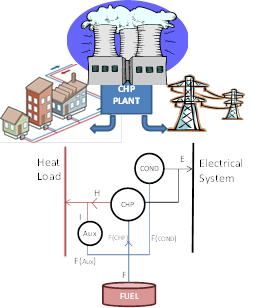 Figure 1: CHP Scheme
In Condense mode, the Fuel Offtake function is given by:
F(cond) = Heat Rate x E(cond)
In CHP mode, the Fuel Offtake function is given by:
F(chp) = CHP Electric Heat Rate Incr × E(chp)
The unit can thus operate in a mixed mode, condense and CHP modes, like in the following expression:
F = F(cond) + F(chp)
F = Heat Rate × E(cond) + CHP Electric Heat Rate Incr * E(chp)
F = Heat Rate × (E - E(chp)) + CHP Electric Heat Rate Incr * E(chp)
Since:
E(chp)= Power-to-Heat Ratio × H
and:
E = E(cond) + E(chp)
it results:
F = Heat Rate × E + ( CHP Electric Heat Rate Incr - Heat Rate ) × Power to Heat Ratio × H
Auxiliary boiler produces heat according to the following expression:
F(aux) = Boiler Heat Rate Incr × I
Notes:
- Input property Heat Load is the total over the station (i.e. The Generator object not per unit).
- Fuel Offtake reported is the total fuel used by the Generator including its auxiliary boiler, if defined, and Heat Fuel Offtake is the fuel offtake from heat production.
- Generation Cost is the electric production cost, and Heat Production Cost is that from heat production (note that VO&M Cost is apportioned according to fuel usage in electric and heat).
- Net Revenue is after subtracting Heat Production Cost
- When a unit goes out-of-service the Heat Load is scaled down, to zero plus the boiler capability if no units are available, to avoid infeasibilities.
3.2. Feasible Operational CHP Region
In this model, CHP units are represented by a feasible piecewise representation of the thermal characteristics of the boiler. This is an acceptably accurate representation of many commercial co-generation power plants currently in use. The quadrilateral area in Figure 2 defines the feasible operating region of the CHP units.
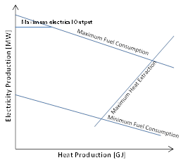 Figure 2: Fuel Offtake Domain
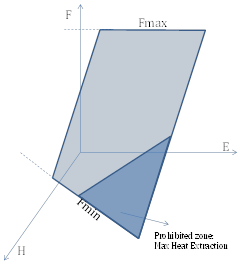 Figure 3: Fuel Offtake Linear Function
The boundaries of the feasible region are defined by:
Maximum Electrical Output
Usually refers to the electro-mechanical limits of the steam the turbine.
Maximum and Minimum Fuel Consumption
Isothermal limits of the boiler. Not that the Min Stable Level in CHP mode is defined by the minimum fuel input of the unit (i.e. flame stability).
Maximum Heat Extraction from Boiler
This value is defined by E > Power to Heat Ratio x H
4. CHP Input Properties
Table 1 lists all properties related to CHP.
| Property | Type | Observations |
|---|---|---|
| Power to Heat Ratio | Key | Defines CHP unit |
| CHP Electric Heat Rate Incr | Key | Required for heat production |
| Heat Rate Incr | Optional | Efficiency for condense mode |
| Boiler Heat Rate Incr | Optional | Ancillary boiler heat production |
| CHP Heat Surrogate Heat Rate Incr | Optional | Notional value for heat fuel offtake estimation. This property is only used for CHP Heat Surrogate Fuel Offtake at the solution |
5. Non-linear With Operational Region
CHP offtake representation can be a non-linear 2nd order polynomial expression. The optimization problem can be solved using QP or MIQP. According to CHP specialized references the fuel offtake function has the following generic non-linear form [1]:
F = ∑_i[c_i (p_i)]+∑_j[c_j (p_i,h_j ) ]+∑_k[c_k (h_k)]
Where ci, ck and cj are the coefficients for Condense mode only units i, CHP units j and pure heat producers k (ancillary boilers), respectively. Note that the term ∑_j[c_j (p_i,h_j ) ] could be any non-linear function of electricity and heat production. In [2], a test system for Combined Heat a Power is developed and analyzed in details. Numerical examples for CHP units have the following form:
F_i = c_(0,i )+c_(1,i ) p_i+c_(2,i ) p_i^2+c_(3,i ) h_i+c_(4,i ) h_i^2+c_(5,i ) p_i h_i
Table 3: Suggested values for the 2nd order polynomial[2]
| Coefficient | Unit 1 [247MW] | Unit 2 [125MW] |
|---|---|---|
| C0 | 2650 | 1250 |
| C1 | 14.5 | 36 |
| C2 | 0.0345 | 0.0435 |
| C3 | 4.2 | 0.6 |
| C4 | 0.034 | 0.027 |
| C5 | 0.031 | 0.011 |
Currently, the non-linear coefficients C4 and C5 are not supported. The following values are supported:
Table 4: Modelling non-linear CHP functions
| Coefficient | Property |
| C0 | Heat Rate Base |
| C1 | Heat Rate Incr |
| C2 | Heat Rate Incr 2 |
| C3 | (CHP Electric Heat Rate Incr-Heat Rate Incr) x Power to Heat Ratio |
| C4 | - |
| C5 | - |
6. Multi-fuel CHP
Multi-fuel definition is supported. There is an important limitation that has to be considered. Since CHP mode efficiency and auxiliary boiler are defined as Generator properties, the fuel offtake function has to also be defined as a Generator property. If the heat rate function (in any of its modalities as explained in the Heat Rate Modelling article) is defined in the Generator Fuels collection, they have to be identical across all fuels. If they differ, a warning will be issued. Fuel Offtake for heat production is:
F = AHR × E + ( CHP Electric Heat Rate Incr - AHR ) × Power to Heat Ratio × H
With:
AHR = ∑(Heat Rate) / N
Where N is the number of defined fuels. The user can still create diversity and scale total cost functions using Transport Charge and/or Shadow Price.
6.1. Waste Heat Market Model
This model applies to CHP units with defined active Market objects. Waste heat is modelled as a linear proportion of the energy loss, which is defined by the difference between the unit's electrical output energy and the fuel input energy. In order to define this proportion, it is required to define the property Heat Generators Conversion Rate in the respective membership. Figure 4 shows the simplified market model where "HR" is the Generator Heat Rate value and 'k' is the linear proportion of fuel heat input for the external market Conversion Rate. When the user defines Heat Rate in multiple bands, the Conversion Rate must be defined using the same number of bands as Load Point. Generators can participate in more than one Market.
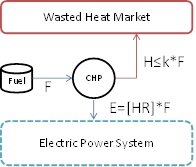 Figure 4: Waste heat market scheme
When using waste heat market model, CHP key properties are ignored. Fuel 'Isothermal' limits are still considered though. The Fuel Offtake function is defined by the offtake for electricity production, as waste heat is produced only if electricity is also delivered to the node(s). The natural objective function, as with any other market model, is profit maximization. The solution will show the optimal trade-off between electricity and heat production, according to the heat waste market prices.
7. Numerical Examples
7.1. Example: Single CHP unit with Power-to-heat Ratio and Auxiliary boiler
In this example, a simple CHP generator is defined using the key properties Power to Heat Ratio and CHP Electric Heat Rate Incr. Figure 5 shows the system modelled. The data for the CHP unit is presented in Table 5.
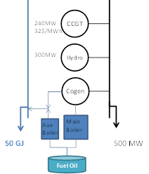
Figure 5: Power to Heat Ratio Numerical Example data
Table 5: Power to Heat Ratio Numerical
| Property | Value | Units |
|---|---|---|
| Max Capacity | 200 | MW |
| Min Stable Level | 50 | MW |
| Heat Rate | 13 | GJ/MWh |
| Heat Load | 50 | GJ |
| Power to Heat Ratio | 3.8 | - |
| CHP Electric Heat Rate Incr | 15 | GJ/MWh |
| Boiler Heat Rate Incr | 1.2 | GJ/GJ |
| Max Boiler Heat | 15 | GJ |
In this example, there is a constant heat load of 50 GJ which can be supplied by the cogeneration of electricity and heat or in combination with the ancillary boiler (as it is defined by the last two properties in the table above). The simulator will understand that the generator has an auxiliary boiler when the property Boiler Heat Rate Incr is defined. For the electrical system load demand, the optimal solution solves the decision problem of optimal electrical dispatch of the CHP unit and its auxiliary boiler in order to meet the heat load demand. The Fuel Offtake function (F) of the CHP unit is:
F = 13 × P + (15-13) × (3.8 / 3.6) × H = 13 × P + 2.111 × H
Feasible operating region of the CHP unit is showed in the Figure 6:
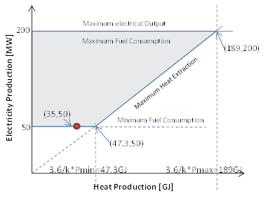 Figure 6: Feasible Operational Region of CHP
The red dot in the figure shows the results of the economical dispatch of CHP. The rationale for the dispatch solution lies in that the CHP unit for electricity production is more expensive than its alternatives CCGT and Hydro units. So the operation of CHP in this case is bounded at its lower electricity production range (50 MW). The high efficiency auxiliary boiler is required at the optimal solution. The heat load demand is then satisfied from 15 GJ (max capacity of ancillary boiler) and 35 GJ from the co-generation plant.
Pricing AnalysisFrom the optimal solution, an increment in the heat load demand will affect the electrical and heat dispatch of the co-generation plant and will also affect the other unit's dispatch. The shadow price of the heat balance constraint (i.e. the dual variable of (2 4)) is 33.77 $/GJ. Since no other constraints would bind in this simple linear model, an easy exercise can show that an increase of 1 GJ of heat load would increase the total system cost.
This is:
∂Fo/∂H≈(ΔTotal Cost)/ΔH=(Fo(51GJ)-F(50GJ))/((51-50))
Following the same numerical example, this leads to:
∂Fo/∂H≈19104-19070.22=33.77
The explanation comes from the gradient of the Lagrangian function at the optimal solution. Assuming μ the Lagrange multipliers and Q the set of active constraints and assuming in advance that the heat load constraint is active:
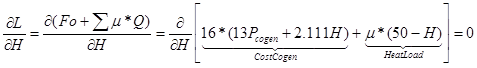 Figure 7: Eq. of derivative
μ=16*2.111=33.777 In practical terms, the heat price 33.77 $/GJ is the competitive price of heat production considering the electrical system and the co-generation capabilities of the power plants.
7.2. Example: Two CHP Units for the Same District Heating Load Demand
This case is an extension of the previous example. In this case the CCGT waste heat is assumed to be also connected to the district heating system.
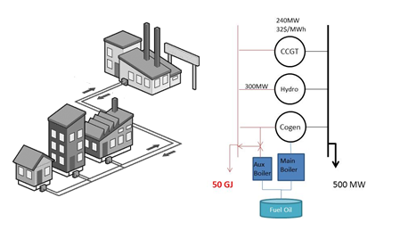 Figure 8: District Heating Problem
In order to model this feature, the following changes are required:
- Cogen Heat Load value is 0 GJ.
- CCGT Power to Heat Ratio must be defined.
- Add a generic Constraint for the heat balance: H(CGGT) + H (Cogen) = 50 GJ.
Table 6: CCGT Power to Heat Ratio Required data
| Property | Value | Units |
|---|---|---|
| Heat Rate | 6 | GJ/MWh |
| Power to Heat Ratio | 1 | - |
| CHP Electric Heat Rate Incr | 11 | GJ/MWh |
The following Constraint"Compete-Heat" is required:
Table 7: Compete-Heat Constraint
| Collection | Property | Value |
|---|---|---|
| Compete-Heat | Sense | = |
| Compete-Heat | RHS | 50 |
| Constraint(Compete-Heat).Generators(cogen) | Heat Production Coefficient | 1 |
| Constraint(Compete Heat). Generators(cogen) | Heat Production Coefficient | 1 |
The optimal 'electrical' dispatch is:
| Generator | Property | Value | Units |
|---|---|---|---|
| CCGT | Generation | 200 | MW |
| Cogen | Generation | 0 | MW |
| Hydro | Generation | 300 | MW |
The co-optimization of heat and power also leads to the following heat dispatch solution:
| Generator | Property | Value | Units |
|---|---|---|---|
| CCGT | Heat Production | 50 | GJ |
| Cogen | Heat Production | 0 | GJ |
Even though results may look trivial, the formulation can be extended. Co-optimization is extended to complex transmission-constrained power systems, ancillary requirements, etc. Any number of co-generation plants can be defined for the same district heating system. CHP units or any other co-generation plant may have the option to supply its own 'fixed' heat load and additional waste heat can participate in complex district heating networks.
7.3. Example: Waste Heat External Market
Suppose that there exists an external heat waste competitive market and cogen plant can offer its waste heat. In this case the dispatch problem of cogen solves the trade-off between generating electricity where it is not competitive and may even have losses compared with a demand response function of the heat market. The solution should maximize the profits considering the revenue from electricity and heat markets. The properties related to the Market "Heat" are shown in Table 8.
Table 8: Market for Heat
| Collection | Property | Value | Units |
|---|---|---|---|
| Generator | Heat Rate | 8.5 | GJ/MWh |
| Market Heat Generators | Conversion Rate | 0.29 | GJ/GJ |
In this example the generator has a constant Heat Rate of 8.5 GJ/MWh. This is an equivalent efficiency of 3.6 / 8.5 = 42%. Here, 3.6 is the constant [MWh/GJ] energy conversion value. Thus the gross waste heat is 58%. Assuming that half of this is lost before it can be used in heating the Conversion Rate to usable heat is 0.5 0.58 = 0.29.
8. Heat Storage and Electric Boilers
CHP plant can be configured with heat storage. In addition, dedicated electric boilers can also be modelled. See the separate article Heat Storage.
9. References
1. Guo,T., Henwood, M.I., van Ooijen,M. "An Algorithm for Combined Heat and Power Economic Dispatch". ''IEEE Transactions on Power Systems''. Vol. 11 No. 4. November 1996.
2. Algie,C., Wong,K.,P. "A Test System for Combined Heat and Power Economic Dispatch Problems". ''2004 IEEE International Conference on Electric Utility Deregulation, Restructuring and Power Technologies''. (DRPT2004). April 2004. Hong Kong.
3. "Combined Heat and Power (CHP) and Statistics". ''Joint IEA/Eurostat Annual Questionnaire Training Workshop''. IEA, Paris 29 - 31 October 2001.