Creating Zone Definitions and System Diagrams
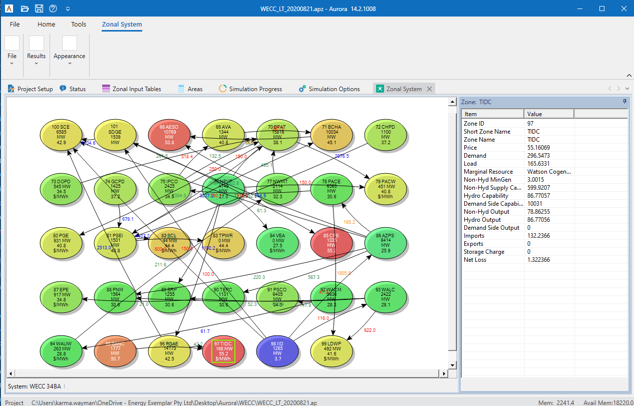
The Zone Definition table is used to develop regional or market consolidation systems which isolate areas, combine areas and run specific areas within the entire input database. The System Diagram displays the selected system of zones in graphical form. Follow the steps below to create a new Zone Definition and System Diagram.
Create a Zone Definition
-
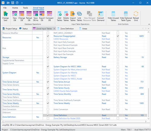
Select the Zonal Input button on the Home Tab Ribbon to open the Input Data Assumptions window for the Zonal Input Tables.

-
Select and open the Zone Definition Table.

-
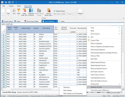
Place the cursor in the top left corner of the data table and right-click to select the Selection To Excel (w/Headers) option from the menu.
-
The Zone Definition table is now in an Excel worksheet.
-
Delete all records besides the header or if desired, copy/paste an entire existing system at the bottom of the Excel worksheet to use as a template for the new system definition.
-
Populate the columns as follows (instructions assume a copy/paste of existing system):
-
Report Zone - contains a True or False statement and is used to assign output reporting for specific zones. If Selected is not set in Output Reporting Options portion of the Table Selection form of Simulation Options, the model will report only on the items selected in this column.
-
System ID - contains the number of the existing system and will need to be changed to a number not already included in the table. Copy this new number to all the zones in the new system. For example, if the last system ID is 8, this ID will need to be changed to 9 and copied to all the zones in the system.
-
System Name - contains the existing name of the system. Enter a unique name for the new system and use this name for all the zones in the new system, as was done above.
-
Zone ID - contains the current zone numbers. These may or may not need to be renumbered. The numbers in this column will be used for the zone numbers in the System Diagram and for output.
-
Zone Name - contains the existing names for the zones in the system. These should be changed to identify the new zones for output reporting.
-
Short Zone Name - contains the short name that identifies the zones and will display in the System Diagram nodes.
-
Run Zone - contains a True or False statement. True means the zone will run in the system. False means the zone will not run in the system.
-
Org Area 1-60 - contain the area number, as specified in the Areas table, for each area in the zone. Input area numbers in the various Org Area # columns to add areas to each zone. (Remember to remove these area numbers from the original zones, if necessary.)
-
![]() NOTE: All the areas in the database must be assigned a position in the new system, regardless of whether they will be run. We recommend that areas which are not running be consolidated in the same zone.
NOTE: All the areas in the database must be assigned a position in the new system, regardless of whether they will be run. We recommend that areas which are not running be consolidated in the same zone.
-
If needed, add new rows to create additional zones in the system.
-
When the new system definition is complete, select and copy all the new record columns and rows.
-
Return to Aurora and the Zone Definition table. Place the cursor in the first cell of the last row in the table and right-click to select the Paste>Paste Append option from the menu.
-
Close the Zone Definition table and save the changes using the Save Edits to DB button on the Data Assumptions Toolbar. (Change Sets are not recommended when creating new systems, but alternately the Save to Memory button on the Change Set window can be used to temporarily hold the changes in the table.)
![]() NOTE: Editing an existing system or adding a new one to the Zone Definition table will require the creation of a new System Diagram.
NOTE: Editing an existing system or adding a new one to the Zone Definition table will require the creation of a new System Diagram.
See Creating a System Diagram for more information.

|
|
![]() Creating Zone Definitions and System Diagrams
Creating Zone Definitions and System Diagrams
